| |
|
|
| |
The engineering firm you work for has been engaged to set up a quality control program for a company that remanufactures engine components. As a first step in the study you must assess the characteristics of various measurement tools and techniques. The findings of the investigation will enable you to formulate realistic goals for the quality control program and to implement appropriate regular checks on the accuracy of measurement instruments. Your report must indicate the accuracy, resolution, range and repeatability that should be expected from each measurement tool as well as special situations which require or prevent its use. Specific results of your test are to be presented in tabular form.
EQUIPMENT - Micrometer Measurements
- gauge blocks
- steel balls
- vernier micrometers
- steel bolts
- engine crankshaft
EQUIPMENT - Caliper Measurements
- gauge blocks
- vernier and digital calipers
- metal part
EQUIPMENT - Surface Table Measurements
- gauge blocks
- sine bar
- surface table
- dial gauge with magnetic base
- engine camshaft
- inclinometer
CAUTION: When working with gauge blocks and other finely machined objects, such as the surface table, avoid touching the metal surface with your hands. Salty perspiration from your skin will form acids that rapidly corrode the surface. Wear protective gloves.
Procedure - Micrometer Measurements
1. To become familiar with reading a vernier micrometer, check for zero, anvil and screw error. Use gauge blocks and a steel ball to check for anvil error. Use three different gauge blocks to check screw error over the range of the micrometer. Try to minimize error due to torque variations by using the slip clutch on the micrometer. Each group member should measure the dimension the same gauge block to determine micrometer precision. Tabulate your results.
2. Each group is to measure the diameters of one sample of 20 bolts, from a larger population, to determine size variations. (bolts in each sample have been identified with a different colour of paint) Using a micrometer, each group is to check the diameters of one set. Account for zero error in the micrometer, but ignore screw and anvil error. In addition to recording the dimension of the bolts in your sample, obtain the readings from another group in your lab section (40 readings total).
3. Using the 50-75 mm micrometer measure the journal diameter of each of the four throws on the crankshaft. On each journal measure at two locations, 90o apart.
4. Measure the variation in thickness of the disk brake rotor provided. Measure at least four positions on the rotor to determine the maximum variation. If the variation exceeds a manufacturer’s tolerance the rotor must be resurfaced or replaced.
Procedure - Caliper Measurements
1. Check the zero error of both a digital and vernier caliper. Using at least three different gauge blocks calibrate the calipers over a 0 - 150 mm range. Check the
precision of the vernier and digital calipers by having each member of the group measure the same gauge block. Note what types of measurements the calipers can be used for. Note the range and resolution of each type of caliper.
2. You have been provided with a metal part to be measured with the vernier caliper to illustrate the versatility of the calipers. Use the vernier caliper to measure the dimensions of the metal part. Record the dimensions on a sketch, neglecting the zero and scale error.
Procedure - Surface Table Measurements
1. Mount the dial gauge and magnetic base on the surface table. Check the accuracy of the dial gauge as follows. Wring together two or three gauge blocks to make a stack approximately the same height as the camshaft when mounted in v-blocks. Note that the stack of blocks serves only as a reference point for calibrating the dial gauge and ensures that the gauge is calibrated at the same point in the range that will be used for measurements. (It is not necessary to calibrate over the entire range if the instrument is only to be used in a small portion of the range.) After zeroing the outer units scale on the dial gauge, add a small gauge block (approximately 1 mm) to the stack and record the change in dial gauge reading for this known displacement (this allows you to determine accuracy). Repeat this procedure a few times to establish precision for the dial gauge.
2. Carefully remove the gauge block stack and replace it with the camshaft. Determine the “run out” of the centre bearing by carefully rotating the camshaft under the dial gauge and determining the difference between maximum and minimum readings. Deviations from true can be caused by wear, a bent shaft or
poor machining. Making this type of measurement allows one to decide whether the camshaft is usable. Determine repeatability of the procedure by having each member of the group set up the dial gauge and determine the run out.
3. A sine bar is used to align machine tools or set surfaces to a specified angle for calibrating other angle measurement instruments. Check the surface table for level. Using the sine bar and gauge blocks construct three angles between 0 and 45 degrees as specified by your instructor. Use the angles constructed to calibrate the inclinometer. Be sure to list all the block sizes used in constructing each angle so an estimate of the uncertainty of the constructed angle may be made. Choose one angle and have each member of the group reconstruct it to determine precision. (Remember that to determine precision the stack of gauge blocks should be taken apart and re-wrung.) Record the inclinometer manufacturers accuracy specification.
Report
1. Prepare a table showing the accuracy, resolution, precision and range of the calipers (both digital and vernier), micrometer, inclinometer, and dial gauge/surface table system. For the dimensional measurement instruments, indicate accuracy using units of length (ie + 0.002 mm) rather than using a percentage of range or percentage of reading.
2. Discuss considerations which would require the use of a particular measurement instrument and indicate potential sources of error.
3. You measured various automotive parts using micrometers. Calculate the mean and standard deviation of each set of measurements. Are any points suspect?Can you expect the same repeatability uncertainty when using the 50-75 mm micrometer as with the 0-25 mm micrometer?
4. Make a schematic drawing of the method used to measure the camshaft run out. The uncertainty in your estimate of run out can arise from several sources - procedural or instrument calibration usually being dominant. Estimate the run out and the uncertainty associated with this estimate. What do you think is the dominant source of uncertainty?
5. Calculate the mean and standard deviation of each sample of bolts. Are any data points suspect? Are the two samples of bolts from the same population? If so, estimate the mean of the population. Show the uncertainty associated with this estimate. Where does the uncertainty come from? Include the analysis in the report Appendix.
6. Sketch the set up used to construct the required angles on the sine bar. Estimate the probable error in constructing each angle assuming L = 127 mm ± 0.05 mm and class B gauge blocks, which have a ±2.0 × l0-4 mm uncertainty. Does the inclinometer meet the manufacturers specification for accuracy?
7. Prepare a scale drawing of the metal part measured using the vernier caliper. On the figure, show all dimensions as well as the uncertainty associated with each. (Assume the uncertainty in each measurement is the greater of the accuracy or the repeatability uncertainty).
Table 1 Instrument Characteristics
| Instrument |
Resolution |
Range |
Accuracy |
Precision |
| Vernier Caliper |
|
|
|
|
| Digital Caliper |
|
|
|
|
| Vernier Micrometer |
|
|
|
|
| Digital Micrometer |
|
|
|
|
| Dial Gauge |
|
|
|
|
| Inclinometer |
|
|
|
|
Table 2 Disk Brake Rotor Measurements
| Reading |
Thickness |
| 1、 |
|
| 2、 |
|
| 3、 |
|
| 4、 |
|
Table 3 Crankshaft Journal Measurements
| Journal |
Reading 1 |
Reading 2 |
| 1、 |
|
|
| 2、 |
|
|
| 3、 |
|
|
| 4、 |
|
|
Table 4 Bolt Measurements
| Measurement |
Bolt Sample 1 |
Bolt Sample 2 |
| 1 |
|
|
| 2 |
|
|
| 3 |
|
|
| 4 |
|
|
| 5 |
|
|
| 6 |
|
|
| 7 |
|
|
| 8 |
|
|
| 9 |
|
|
| 10 |
|
|
| 11 |
|
|
| 12 |
|
|
| 13 |
|
|
| 14 |
|
|
| 15 |
|
|
| 16 |
|
|
| 17 |
|
|
| 18 |
|
|
| 19 |
|
|
| 20 |
|
|
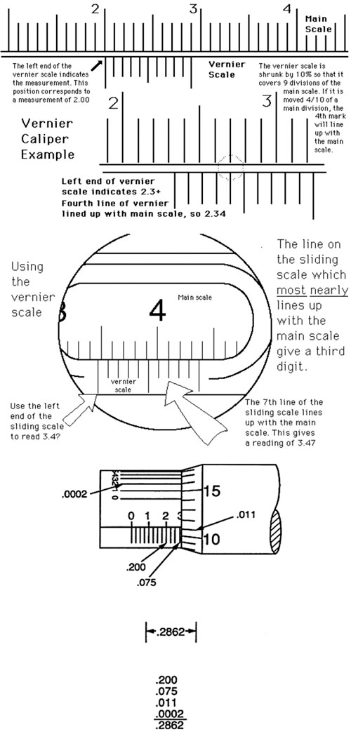
Figure 2 Reading a Vernier Micrometer
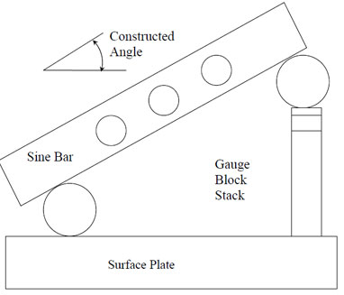
Figure 3 Constructing Angles Using a Sine Bar and Gauge Block Set (note: sine bar length is 127 mm + 0.05 mm) | |
|
|
|
|
|